Click on any picture for a better view
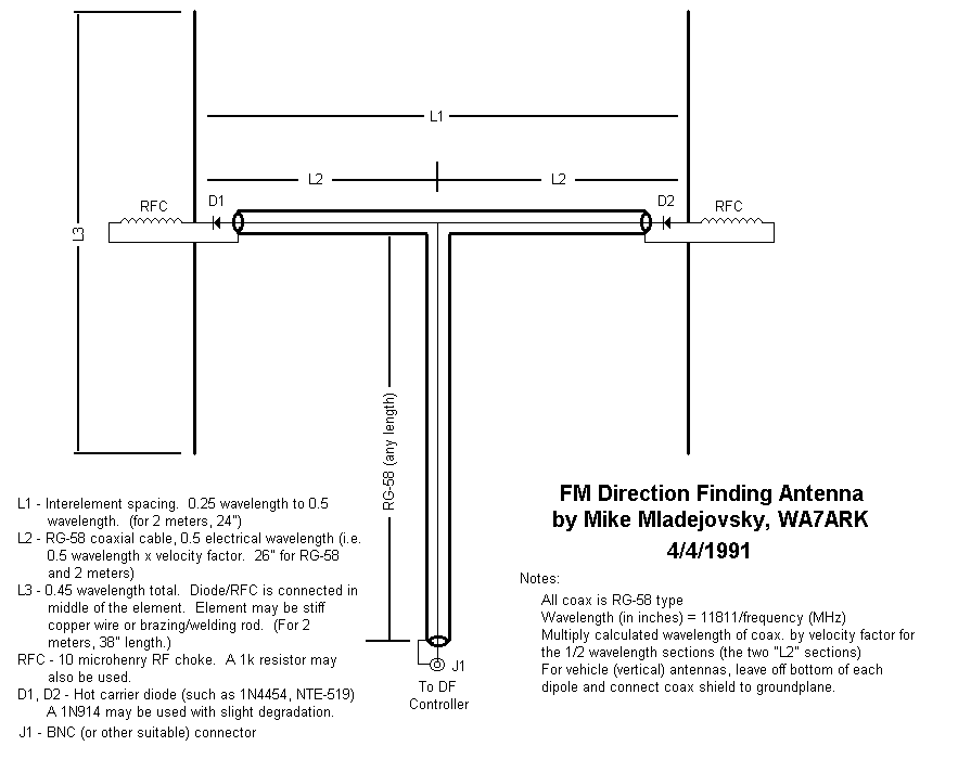
Background:
I had originally gotten the schematic for the Audible DF Unit at the about the time the schematic was drawn (back in 1984) and immediately built the circuit board, but didn't ever put it in a box. As a result, the circuit board spent much of its time kicking around in various configurations and states of disrepair, needing to be kludged back together each time it was called into service. Eventually, I got around to putting it in a real box: This was a definite improvement as it had not only provided for a more rugged package, but it included a built-in speaker, and an earphone connector (that muted the speaker.) Along the same time, I had built several antennas, each one being an improvement over the previous one: The one described below is the current incarnation.
|
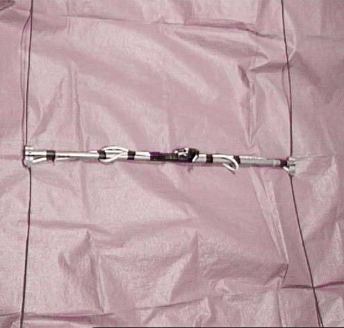
The photograph to the left shows the completed antenna as described
here.
(Yes, I know, it is hard to see detail, but it should give you the
general
idea.) Although this antenna uses an aluminum boom, the
effects
of a metallic boom is minimal due to it being at right angles to the
elements.
RG-58 is used for the phasing lines: Even though the loss of
RG-58
is a bit high on 2 meters, its use dictated not by loss
concerns,
but the the small size of the coax make it more suitable for this
application.
 |
One of the trickier aspects of antenna construction is how to construct the "dipole" feed. This requires not only electrical but mechanical separation of the two halves of the element. The picture to the right shows how this was accomplished: Two opposing holes were drilled in a piece of polyethylene (taking care that they do not cross each other, or connect with the bolt that holds it to the boom.) To secure the elements (which are pieces of 1/16" brass brazing rod) into place, small pieces of wire were soldered on either side of the plastic block to prevent it from sliding through on either side. On the top one can see epoxy used to provide additional ruggedness. On the bottom, silicone sealant protects both the inductor (barely visible through the sealant) and the diode, as well as providing some mechanical rigidity to the coax connection.
The array is marked in several places with arrows to not only help the user determine which direction is up, but which is the front and back: If this was not done, it would be necessary to determine empirically which was the top and the front every time the antenna was to be used. Even if this is not done, it is fairly easy to determine the orientation through experimentation on a signal of known origin.
 |
The picture to the left shows the completed, packaged "Audible
FM DF" unit. The enclosure was obtained at Radio
Shack
(several years ago - they no longer carry that particular model) and it
has a handy compartment for the 9 volt battery. Notice also the
holes
drilled for the speaker, as well as the front-mounted power-on
indicator.
Although not easily visible in this picture, the speaker jack is on the
left side and the two BNC connectors are on the right side of the box.
 |
The interior view of the box (to the right) shows how the
various
pieces are arranged. The speaker is simply epoxied to the back of
the front panel and the earphone jack (which is the same size as found
on personal stereo headphones) is mounted to the left and slightly
above
the speaker. The circuit board itself is mounted to the back half
of the enclosure using plastic bosses molded into the body of the
enclosure
itself. Note that the placement of the speaker allows for
clearance
to the back of the speaker, and the placement of the on/off switch to
the
left of the battery compartment. It is worth mentioning that the
on/off switch (a 2-position slide switch) has most of its lever cut off
so that it is nearly flush with the enclosure: This prevents the
switch from being snagged on other objects and the unit being
inadvertantly
turned on, resulting in a dead battery when you need to use it.
 |
The only critical wiring in the unit is that associated with the RF connections. The picture to the left shows how this was accomplished: The BNC connectors are mounted on a small piece of printed circuit board material which is, in turn, mounted on the side of the enclosure. Not only does this piece of circuit board provide added mechanical rigidity, but it provides for a solid ground plane between the two connectors, preventing signal leakage/ingress at this point. The connectors are mounted as close to each other as practical (but not so close that it is difficult to attach and remove them) and lead length are kept short.
Return to the UARC DF circuit page,
The
UARC RDF page or The
UARC home page
This page updated on 20020705